


Date: Jan 04, 2023 Read: 17833
Share:


With the rapid growth of EDSFF form in server capacity in recent years, EDSFF will redefine the form factor specifications of the next generation SSDs for servers with its advantages in capacity, scalability, performance, maintainability, manageability, heat dissipation and power management.
Overview of EDSFF
Currently, EDSFF has the following three interpretations: Enterprise and Data Center Standard Form Factor (Standard); Enterprise & Data Center SSD Form Factor (SSD); and Enterprise and Data-center Scalable Form Factor (Scalable), except with slightly different emphasis on their connotations. It is now maintained by Storage Networking Industry Association (SNIA) as part of the Small Form Factor Technology Auxiliary Technical Working Group (SFF TA TWG).
EDSFF enables a range of enterprise and data center SSD form factor standards to maximize the adaptation with 1U/2U servers, as outlined below:
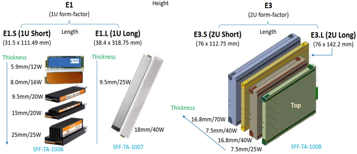
Fig. 1
For the evolution of the SSD form factor standards, some key elements to be considered for these standards can be understood from the following four dimensions from the perspective of hardware:
EDSFF is divided into E1 and E3 series, each series is subdivided into Long and Short versions, namely E1 (E1.L, E1.S) and E3 (E3.L, E3.S), which are classified into different models according to different thickness and heat dissipation configuration: 40W and 70W versions are available on the basis of 20W and 25W versions; the number of PCIe Lanes is also increased by x8 and x16 on the basis of x4 (E3 width can be met, E1 maximum x8), to meet the higher read-write performance of ESSDs. The specific dimensions for EDSFF in various form factors are summarized as follows:
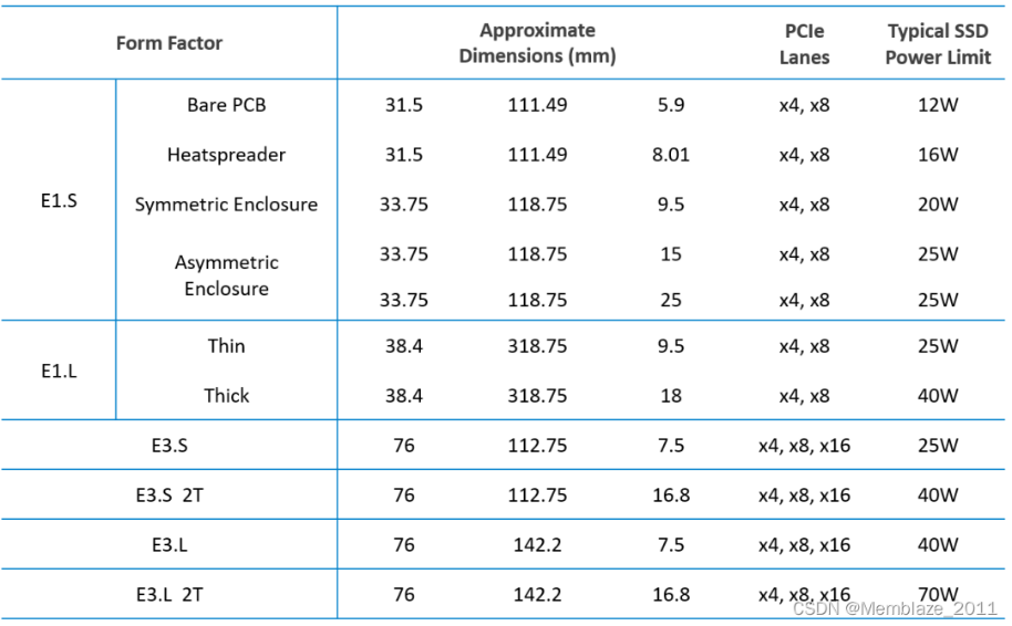
Fig. 2
EDSFF——Hardware Interface Standardization
SFF-TA-1002 connector standard defines a multi-channel card edge connector, specifying four high-density connector sizes: 1C, 2C, 4C, and 4C+. The 1C connector serves as a common basis for all other sizes, with 1C supporting up to 80W of 12V main and 3.3 Vaux auxiliary power supplies, a set of sidebands and power management IC pins, and up to 8 high-speed differential pairs. 2C builds upon 1C and provides up to 16 high-speed differential pairs. Similarly, 4C builds upon 2C and provides up to 16 additional high-speed differential pairs.
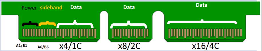
Fig. 3
SFF-TA-1002 defines dimensions that fit PCIe x4, x8, and x16, and longer cards can be plugged into narrower card slots thanks to the recess design in the card edge connector. Such connector affords sufficient signal integrity for a data rate of at least 56 GT/s through NRZ (non-return-to-zero) coding, thus it is more forward-looking than most existing PCIe signal connector standards in terms of implementation.
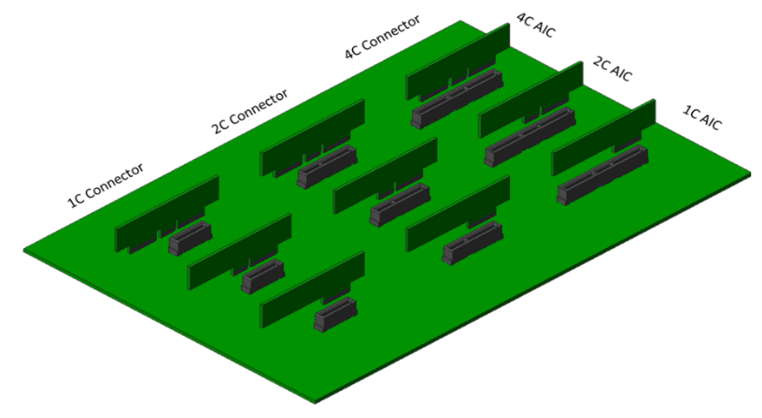
Fig. 4
E1 and E3 use the same connecting finger, so they have higher signal quality while ensuring good compatibility. The new server backplane connector is of smaller form factor, so as to achieve the goals of simplifying the internal design of the server, optimizing the air channel, and enhancing the heat dissipating air flow of the server. To maximize interoperability, the SSD form factors of EDSFF family share a common connector standard.
EDSFF——The Evolution from M.2 Form to E1 Form Factor
M.2 is mainly used for notebooks. In the case of 3.3V power supply, the maximum power will be limited, and it usually requires a heat spreader when the power consumption is up to 8-12W. The form factor of M.2 will face many challenges when used on 1U servers:
Firstly, in heat dissipation, PCIe SSD requires a large heat spreader;
Secondly, it does not support hot plugging, because the connector is not
designed for hot plugging, in addition, it is difficult to maintain the fixedly
installed SSD; Thirdly, the space utilization of 1U rack (1U=4.445cm, M2 width=2.2cm)
is less ideal than expected.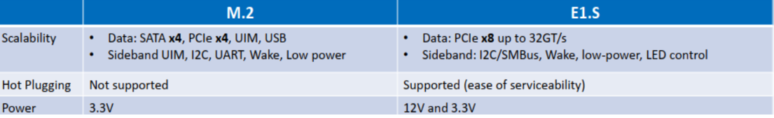
Fig. 5
E1.S form shows huge advantages in the use of 1U servers at data centers:
For different power requirements, E1.S adopts different standard enclosure and heat spreader sizes: For cards with power consumption less than 20w, symmetrical enclosure/heat spreader with a thickness of 9.5mm can be used; for higher power applications, an asymmetric heat spreader is designed to a thickness of 25mm and to allow 25w power consumption. A symmetrical 9.5mm thick enclosure is sufficient for most SSD use cases; the configuration of 25mm asymmetric enclosure + heat spreader is more suitable for non-SSD devices; for application scenarios focusing more on high performance, E1.S with thicknesses of 15mm and 25mm is a more ideal choice.
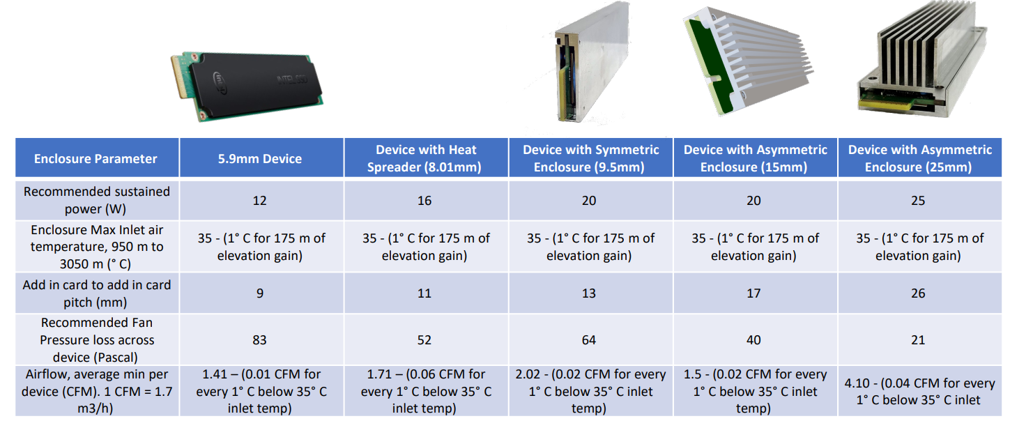
Fig. 6
EDSFF——The Evolution from U.2 Form to E3 Form Factor
U.2 2.5-inch SSD is the main form of enterprise NVMe SSD deployed in enterprises and data centers, which can be mixed with the existing HDD, and features good compatibility and high flexibility. With the same form factor design and SFF-8639 connector, it is compatible with SAS, SATA and PCIe. It is defined in SFF-8201, the length is 101.85mm (max.), the width is 69.85mm, and the thickness varies from 5mm to 19.05mm. The thickness of commonly used notebook SSD is 7mm, and that of ESSD is 15mm.
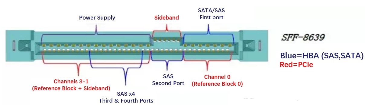
Fig. 7: From Online Picture
From SFF-8639 interface in the figure above, PCIe is marked in red, which allows use of 4 channels, but limits the room for higher bandwidth and performance improvement. In addition, the thickness of ESSD is 15mm, which limits the density improvement compared with the thinner 7.5mm E3.S SSD.
The height of E3 allows SSDs to use x4, x8 or even x16 PCIe interfaces, with higher achievable bandwidth and configurable operating power. E3.S and E3.L are divided into “1T” and “2T” thickness versions (T=Thickness, 1T: thickness of 7.5mm, 2T: thickness of 16.8mm), 4 versions in total. Among them, E3.L 2T even enables 70W full power operation, supporting SSD to achieve higher and stronger performance.
E3.S is the version of E3 that is closer in size to U.2 2.5-inch SSD, and
both of them can share a computer case, to achieve the mixed deployment of SDDs
in different types. The smallest connector size of E3 device, the 1C model, is
23.88mm wide, which is of the same size with M.2 connector. The 4C model that
supports PCIe x16 links is 57.02mm, which is significantly smaller than the
SFF-8639 of U.2. The backplane can be made smaller to reduce the flow
resistance of heat dissipation. Better heat dissipation enables E3.S/2T to support
up to 40W, thus adapting to the performance of PCIe Gen5 and future Gen6. Moreover,
some server manufacturers are also exploring new devices based on E3, such as
GPU, FPGA, NIC, etc. EDSFF E3 will also bring
more possibilities for enterprise applications in addition to storage.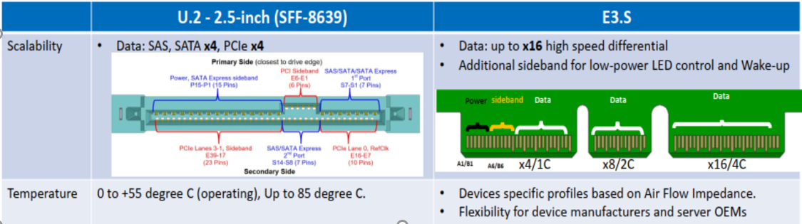
Fig. 8
The Application Scenarios in Servers:
EDSFF is a tailored design standard for enterprise and data center SSD form
factor, which enables petabyte-level data storage capacity on 1U servers, and
enables more superior data storage performance on 2U servers. (1U=4.445cm,
2U=4.445cm*2=8.89cm)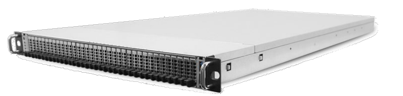
Fig. 9: From Online Picture
EDSFF standard is optimized for enterprises and data centers according to the characteristics of NAND Flash, which gradually gets rid of the influence from HDD form factor, and affords more flexible and more scalable storage solutions, becoming the evolution trend of data center SSD standards.
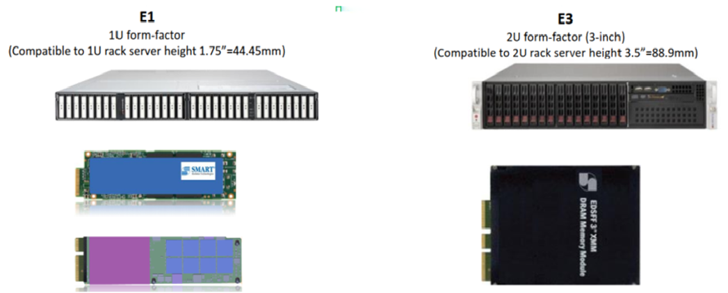
Fig. 10
Compared with the M.2 standard, the E1.S specification has a higher storage density, because it can accommodate two rows of NAND particles to meet the storage scheme of high-capacity super-scale servers. In addition, it has a shorter form factor than that of E1.L, enabling a more efficient thermal design for 1U servers.
E1.S allows significant reduction in SSD volume, up to 32*9.5mm E1.S SSDs can be accommodated in a 1U server, which is more than three times the density of using a 15mm U.2 SSD solution. While the 15mm E1.S SSD, which is of the same thickness as a traditional 2.5-inch SSD, allows the accommodation of 24*15mm E1.S SSDs in a 1U server, the 15mm E1.S SSDs can use the extra space for heat dissipation and allows the use of 25W devices. Its compact size also allows server manufacturers to maintain a certain number of E1.S interfaces on the front panel while also affording a certain number of PCIe/OCP NIC slots, or be used for mixed deployment with E3 and U.2 SSDs, making it very flexible.
Although E1.L accommodates more Flashes, it is not conducive to high-speed signal routing because it is too long, requiring the coordinated synchronous change of the server. The resilience of E1.L SSD becomes larger. Once bent, it is apt to cause PCB damage and resultant lower hardware reliability. The purpose of E1.L is to provide a large-capacity SSD solution for 1U servers.
The E3.S specification can be installed vertically in 2U servers or horizontally in 1U servers, available with two thicknesses, 7.5mm and 16.8mm. In a traditional 2U server, the number of front U.2 SSDs is up to 24, and after changing to E3.S/2T, it can accommodate 23*SSDs (the thickness of 2T is 16.8mm, the thickness of U.2 is 15mm, so one less SSD for the latter); However, E3.S/1T can achieve up to 46 hot plugging spaces, quite obvious in density advantage.
The E3.S needs to be placed horizontally in the 1U case. 10 can be accommodated (the same number as U.2) in 16.8mm thick SSDs, and 20 can be accommodated in 7.5mm thin SSDs, which is twice as many as U.2.
Conclusion:
All EDSFF form factors share the same protocol (NVMe), the same interface (PCIe), the same card edge connector (SFF-TA-1002), and the same pin arrangement and function (SFF-TA-1009). Part of the mainstream form factor standards and application scenarios are selected for comparison, as shown in the figure below:
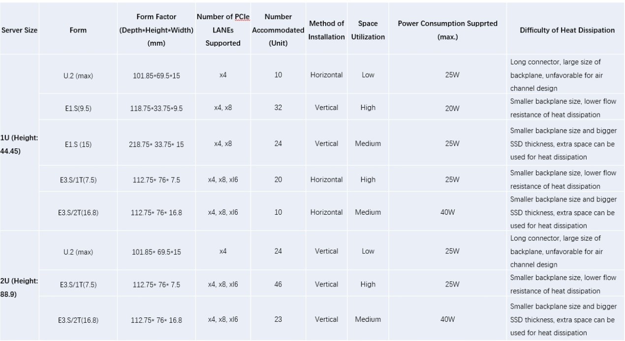
Fig. 11
After PCIe5.0, the bandwidth and performance as well as the electrical characteristics supported by U.2 and M.2 can hardly meet the requirements, switching to E1.S and E3.S is an inevitable trend.
E1.S is the best choice in the evolution of EDSFF standard, which changes width for length and shares the same PCB. In order to meet the heat dissipation capacity of PCIe Gen5 and SSDs of high versions, 9.5mm and 15mm SSDs will become the mainstream choice.
The E3.S form is close to the U.2 form, and the traditional server architecture is more compatible with the design, which can be naturally transitioned to the E3 form. The extra height of E3 allows the use of x8 and x16 connectors, affording more channels to support bigger bandwidth. 2U can accommodate a larger number of E3.S/1T SSDs with smaller thickness, and the density can be further improved. SSDs with bigger thickness can meet the requirements of higher power consumption.
The laboratory test has been completed for UnionMemory’s SSD verification version of the E3.S 1T form, and the official product will be released soon. In the near future, we will also release the products of E1.S (9.5mm/15mm) forms and E3.S/2T form for applications with large capacity and high heat dissipation requirements, let’s look forward to them!
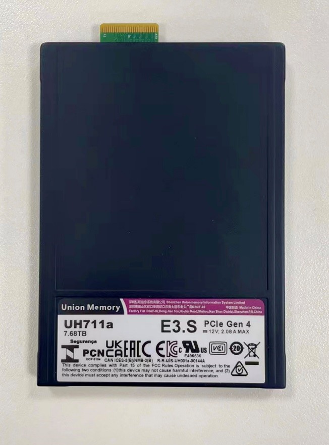
All test verifications have been completed for UnionMemory’s SSD verification version of the E3.S 1T form. It provides 1C connector interface size, and its performance and reliability specifications meet the requirements of the use for various scenarios. UnionMemory’s E3.S 1T product form will be released soon, implying that Union Memory has made further achievements in cutting-edge technology trends and R&D innovations, and UnionMemory’s SSD products have reached the domestically leading level, which also represent the domestic manufacturers are coming to the top among players in the global SSD industry.

“Chip” Knowledge You Must Read | Evolution History of NAND Flash Interfaces
Data Storage | Sharing on Application of Information Security Technology in SSD
Address: 19th Floor, Block B, Ramaxel Houhai Center, Nanshan District, Shenzhen
Tel: +86 755-2681 3300
E-mail: support@unionmem.com
